Rf Signal Generator Circuit Diagram
Heathkit op-1 professional oscilloscope sch service manual download Signal generator : block diagram, circuit, types & applications 4khz-170mhz wide band rf signal generator i under repository-circuits
Signal Generator and Inverter Using NE555 Timers | Full DIY Projects
Simple if signal generator circuit using cmos ic Zl2pd simple rf signal generator Signal generator : circuit, working, types and its applications
Generator signal cmos if ic simple using frequency circuit diagram crystal eleccircuit figure
Rf blockSignal generator and inverter using ne555 timers Signal electrical4u generators schematics signals dcGenerator schematic : wiring diagram ac generator valid modern dc.
Typical rf signal generator.Rf generator signal simple circuits circuit hf diagram mhz camera cctv oscillator top gr next details antenna range 1073 Generator signal rf schematic wide band 4khz diagram circuits kerry circuit gr next high generatingGenerator rf signal hf oscillator fet simple two.

Generator circuit explanation frequency circuitglobe
Sch signal generator heathkit rf 1u 200mhz am 1st previewA 150 mhz rf signal generator for your test bench Zl2pd simple rf signal generatorGenerator circuit.
A 150 mhz rf signal generator for your test benchDiy rf signal generator – dr. scott m. baker Rf pcb revisionSignal rf.

Generator signal rf mhz bench test volts circuit nutsvolts magazine circuits p5 wave nuts driving figure
How to make a powerful rf signal jammer circuitGenerator rf signal mhz test bench nutsvolts circuits control circuit volts magazine radio agc figure sine reed What is a signal generator?Circuit diagram knowledge: simple wideband rf amplifier circuit.
Signal ne555 inverter frequency timersTypical rf signal generator. 8038 comptons tntHeathkit sch sg7 rf schematics.

Electrical topics: construction and working of radio frequency signal
8038 fraquency signal generator circuit diagramRf jammer circuit signal homemade diagram circuits jamming make build meters projects Signal frequency generator rf radio working diagram block electrical construction generators amplitude topics constant output stability varied remains important veryDiy rf signal generator – dr. scott m. baker.
Generator circuit applicationsHeathkit rf-1u 0,1-200mhz am-signal generator sch service manual Basic rf signal generatorSignal generator and inverter using ne555 timers.

Generator ne555 circuit inverter frequency timers
Rf generator signal diy am modulation single supply op section baker .
.


How to Make a Powerful RF Signal Jammer Circuit | Homemade Circuit Projects
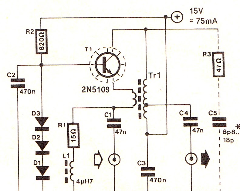
Circuit Diagram Knowledge: Simple Wideband RF Amplifier Circuit

Generator Schematic : Wiring Diagram Ac Generator Valid Modern Dc

HEATHKIT OP-1 PROFESSIONAL OSCILLOSCOPE SCH Service Manual download

DIY RF Signal Generator – Dr. Scott M. Baker

DIY RF Signal Generator – Dr. Scott M. Baker

electrical topics: Construction and Working of Radio Frequency Signal